Today I hooked up my LCD panel to Sparky and got it working. I learned a lot along the way. We sailors have a saying: 'If everything works out perfectly, you haven't learned a thing!'
Checking into the Digistump Forum showed me that I was not alone. However, once you get all your ducks in a row it works quite well.


After sorting that out, the next thing is setting up the hardware. LCD panels come in two flavors. They really are the same thing, but the ones we need usually have another board riding piggy back on the device. You want a panel that is Hitachi HD44780 compatible. The regular versions will hook up to the Arduino quite well, but they require a minimum of six I/O pins. Many of the sketches you will find in collection you downloaded are meant for these screens. Unfortunately we only have SIX pins on the Digispark, so that leaves nothing left for any other purpose. Make sure you have one that is set up for I2C. This only requires two pins! Digistump offers an LCD Shield Kit that includes everything you need to build up your own. You provide the solder and iron.
I found that I already had everything I needed in my spare parts cupboard, so I thought I would do my own. I looked for a schematic of the kit and couldn't find one. Most of the information was clear on the tutorial. I wasn't sure how the two 4.7K Ohm resistors fit into the scheme. I fired off a quick query to support@digistump.com and Erik got back to me right away. Of course they are swamped trying to get product shipped to everyone which means they haven't had a chance to get all the schematics on line. He told me that the resistors were 'pull up resistors' that go between the two I2C lines and +5V. That was all I needed to know.
I2C is a clever way to connect multiple devices together on a single two line bus. Each device is given a unique ID number and can tap in anywhere along the lines. You only need one pull up resistor for each line. Click here for a good I2C tutorial.

One line, SDA, is the data line. The other, SCL, is the clock. One of the devices in an I2C network is know as the 'master'. It controls all the others, which are referred to as 'slaves'. The master can send commands to any of the slaves and can ask any slave to send data back to it. There are numerous I2C sensors available that measure, temperature, pressure, tilt, compass heading, etc. etc. Many of these have ways to manipulate the lowest three bits of the ID so that you can have more than one of the same type in a circuit with unique ID numbers.

- GND
- VCC
- SDA
- SCL
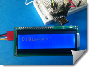
 I plugged the two resistors into the bread board with one leg connected to the 5V bus. I then used male jumpers to hook the other two ends to pins 0 and 2 on Sparky. I had to add male jumpers to the other end of my I2C cable. Hook the White, SDA, lead to Sparky's P0 and the Yellow, SCL, to P2. (In my photo, you will see a green one, I was too hurried to hunt for a yellow one.) The Red and Black leads go to +5V and ground. That's pretty much it.

You can solder a resistor in place of the jumper to limit the amount of backlight for the LCD. Mine was so bright it lit up the whole room, so I've put a resistor there, now it is bright enough.
ReplyDelete